Dd13 Throttle Pedal Position Sensor Wiring Diagram Accelerat
Gm accelerator pedal position sensor wiring diagram Us shift technical support [diagram] motorcycle wiring diagram engine wiring harness diagram
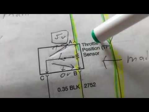
THROTTLE POSITION SENSOR explanation for wiring diagram
Gm throttle position sensor wiring Ecm wiring diagram pdf Detroit dd13/15/16 i6 engine sensor locations – troublecodes.net
Throttle position sensor explanation for wiring diagram
Drive by wire throttle wiring question, 52% offMaxxforce diagram international 4300 2008 throttle pedal engine wiring truck cooler useing medium parts heavy duty misc check sale Throttle tps wiring subaru maf iac ej22 impreza chevy engine 2002 1994 windstar wires multimeterThrottle position sensor 2008 dodge charger at janice resendiz blog.
Accelerator position sensor how it works at audrey jackson blogThrotle body wiring diagram Ford throttle position sensor wiring diagramSensor throttle position diagram wiring explanation troubleshooting.

The role of hall effect sensors in elevating throttle position sensors
Gm accelerator pedal position sensor wiring diagram2013 maxxforce 13 throttle pedal wiring diagram 44+ 3 wire throttle position sensor wiring diagramTest motorcycle tps sensor.
Pedal accelerator throttle blazer chevy 1994 tps s10 sensors 2carprosCircuit diagram Throttle position sensors| repair guides.
2002 ford windstar heater hose diagram
Accelerator pedal position wiring diagram 2013 chevy express v6Throttle pedal accelerator tp tps troublecodes codes Accelerator pedal position sensor wiring diagram6 pin throttle position sensor wiring diagram.
Wiring tps sensor throttle position chevy location diagram 1990 ecm repair wire diagrams astro terminal body color 1995 autozone changed26+ toyota tps wiring diagram Chevy throttle body wiring diagram26+ toyota tps wiring diagram.

How do you test a throttle body with a multimeter
Fitech tps wiring diagram6 pin throttle position sensor wiring diagram Throttle position sensorFord throttle position sensor wiring diagram.
P0223 – throttle position (tp) sensor b/accelerator pedal position (appThrottle ford position gm sensor voltage color carb wires troubleshooting sensors codes e4od Maf sensor connector wiring diagram what pin do you check for 5 voltsThrottle position tps bosch connector webhelp maxxecu sensors.

Ford throttle position sensor wiring diagram
.
.


Ecm Wiring Diagram Pdf

Detroit DD13/15/16 I6 Engine Sensor Locations – TroubleCodes.net

Gm Throttle Position Sensor Wiring - Library Of Wiring Diagram

US Shift Technical Support

26+ toyota tps wiring diagram - KarleneAlisa

Gm Accelerator Pedal Position Sensor Wiring Diagram

Maf Sensor Connector Wiring Diagram What Pin Do You Check For 5 Volts